數值電磁 - 電容模擬器自己寫 (part3/3)
此篇延續[數值電磁 - 電容模擬器自己寫 (part1/3)], [數值電磁 - 電容模擬器自己寫 (part2/3)]
用MATLAB寫一個計算電容的數值模擬器,此篇介紹邊界條件Boundary Condition。
1. 如何給電壓值
2. 如何模擬無限大free space
[如何給電壓值]
我們知道電容C=Q/△V
若有兩個金屬,一個給1V,另一個給0V。
那麼金屬上會自然感應出電荷Q,而感應電荷的量越多,代表C越大。
那麼1V在模擬上是如何加在金屬上的呢?
前兩篇介紹到Laplace Equation。
-🜄²φ = 0
電壓=電位=φ。
常見電容模擬器會將整個金屬視為等電位。
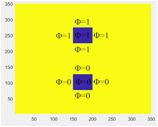
所以模擬上金屬給1V,只要將整塊金屬的φ都強制設定為1V就可。
如下圖,藍色是金屬,其一金屬φ永遠是1(V),另一金屬φ永遠是0(V)。
此類型又稱Dirichlet Boundary Condition[如何模擬無限大free space]
前兩篇介紹到Laplace Equation的有限差分型態。
φ(x,y) = (φ(x-h,y) + φ(x+h,y) + φ(x,y-h) + φ(x,y+h))/4
「x,y點的電位 = 左、右、上、下四個點電位的平均(相加再除4)。」
如下圖
剛我們已將中間的金屬強制給定電壓φ=1V或0V。
而其他空間φ(x,y)可由上式算出,由左、右、上、下四個點電位求得。
有趣的是邊界呢?
例如最左邊邊界φ(1,y),已經沒有更左邊的電位可以用來算φ(1,y)。
例如最下邊邊界φ(x,1),已經沒有更下的電位可以用來算φ(x,1)。
所以邊界上的φ是必經特別處理的,我們稱為邊界條件(Boundary Condition)。
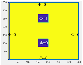
一種邊界條件處理是不管他(不算他),讓邊界φ維持為0。
其實仔細思考,這就等同於外面包著一塊0V的金屬(如同[如何給電壓值]剛剛描述)。
如下圖,整體架構變成3塊金屬,而最外面那圈的電壓為0v。
不難想像,整體電容值會更大,因為多了金屬到外圈的電容。
顯然把邊界φ維持為0不是個好主意,破壞了原本模擬的架構。
但更經常,我們想知道的是只有2塊金屬單純地放在空氣中(或介質)中。
問題就成為,我們如何用運算「有限大」空間,去得到「無限大」空間的結果。
一種近似方法是floating metal或者PMC(Perfect Magnetic Conductor) 邊界條件。
如下圖
常見商用模擬軟體(Ansys, Cadence)都提供金屬Float的功能(電容矩陣後處理)。
先模擬3塊金屬,再將最外圈金屬Float,就得到無限大空間的結果。
或亦可直接給定PMC當邊界條件。
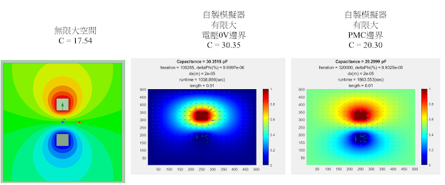
[無限大空間 vs 有限大空間0V邊界 vs 有限大空間FloatingMetal邊界](商用軟體)
下圖場圖是無限大 vs 有限大0V邊界 vs 有限大FloatingMetal邊界(10mm x 10mm)。
可明顯看出有限大FloatingMetal邊界(最右圖)比較近似無限大(最左圖)。
嚴謹的人可能會說,無限大(最左圖)和有限大FloatingMetal邊界(最右圖)還是有點不同。
有限大FloatingMetal邊界只是一個近似手法,若要近似的好,有限大的空間不能太小。
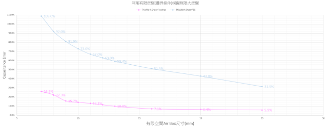
下圖X軸為有限大的空間(airbox)尺寸,Y軸為和無限大相比的誤差。
藍色線是有限大0V邊界,紅線是有限大FloatingMetal邊界
Air box size vs Error
模擬的金屬尺寸為1mm x 1mm,金屬間距邊到邊2mm。
X軸越右邊表示airbox越大,可看到紅線airbox為7mm x 7mm時,誤差為22.6%。
隨著airebox越來越大,30mm x 30mm時,紅線誤差只剩0.9%。
我們僅需計算「30mm x 30mm」的「有限空間」,就能很好的近似「無限大空間」。
不同邊界條件的影響
藍色線是有限大0V邊界
藍線右方即使air box已經很大100mm x 100mm,仍有21%誤差,無法用來近似「無限大」。
紅線是有限大FloatingMetal邊界
如上所描述,紅線airebox為30mm x 30mm時,誤差只剩0.9%,可以用來近似「無限大」。
所以說,有限大FloatingMetal邊界 + 不太小的air box 是用來近似「無限大」的必要兩條件。
介紹自己寫程式模擬PMC邊界條件。
PMC的「表面垂直方向」電場E為0(連結PMC說明)。
E = -🜄φ = 0 ,所以垂直於邊界表面的φ會不變。
在邊界上,最左和最右兩側,「x,y點的電位 = 上、下兩個點電位的平均(相加再除2)。」
φ(x,y)|bc = (φ(x,y-h) + φ(x,y+h))/2
在邊界上,最上和最下兩側,「x,y點的電位 = 左、右兩個點電位的平均(相加再除2)。」
φ(x,y)|bc = (φ(x-h,y) + φ(x+h,y))/2
此邊界條件又稱Neuman Boundary Condition
接著用自製模擬器來算
[無限大空間 vs 有限大空間0V邊界 vs 有限大空間FloatingMetal邊界](自製軟體)
Air box size vs Error
可看到自製軟體和商用軟體有一致的趨勢。
證明PMC當邊界條件(紅線)能近似無限大空間,且隨著airbox越大,近似效果越好(error 5%)。
電位為0(藍線)當邊界條件的話,不管airbox多大,都無法近似無限大空間(error 31%)。
另一方面,透過結果得知,有限差分法+Jacobi Iteration不適合算開放性大空間。
1. 均勻格點airbox讓每一次的iteration時間過長
2. 需要很多次iteration才能收斂(30萬次以上),模擬時間花費4小時以上
------
Reference:
http://www.multiphysics.us/electrostatic.html
https://klimas.paginas.ufsc.br/files/2018/06/chapter-4.pdf
https://www.iue.tuwien.ac.at/phd/nentchev/node28.html
https://physics.stackexchange.com/questions/53455/dirichlet-and-neumann-boundary-condition-physical-example
https://optiwave.com/optifdtd-manuals/fdtd-pmcpec-boundary-conditions-and-plane-wave-simulation/
------
「MATLAB程式碼 - 雙金屬電容器 + PMC邊界條件 」
模擬時間約半小時
clc;clear;close all;
t0 = clock;
disp('Simulation is running...')
%%
for length = [0.010] % 10mmx10mm
%% mesh
dx = 0.02*1e-3; % mesh 0.02mm
meshnum = round(length/dx);
% metal 1
metalsize = round(1*1e-3/dx); % metal 1mmx1mm
start_x1 = round(length/dx/2-metalsize/2);
start_y1 = round((length/2+1e-3)/dx); % 1mm above center
endmetal_x1 = start_x1 + metalsize -1;
endmetal_y1 = start_y1 + metalsize -1;
metalPositiveVolt = ones(meshnum);
metalPositiveVolt(start_x1:endmetal_x1,start_y1:endmetal_y1)=0;
% meta2
start_x2 = start_x1;
start_y2 = round((length/2-1e-3)/dx)+1; % 1mm below center
endmetal_x2 = endmetal_x1;
endmetal_y2 = start_y2 - metalsize +1;
metalPositiveVolt(start_x2:endmetal_x2,start_y2:-1:endmetal_y2)=0;
% phi Initial guess
phi = rand(meshnum,meshnum); %隨機初始化空間電位
% initial E,D,phi,Epsilon
E = zeros(meshnum);
Ex = zeros(meshnum);
Ey = zeros(meshnum);
D = zeros(meshnum);
Dx = zeros(meshnum);
Dy = zeros(meshnum);
Epsilon = ones(meshnum);
% plot strcture
structure = Epsilon.*metalPositiveVolt; % plot structure
figure;pcolor(structure');colorbar;shading interp;
subtitle({['0 is metal'],['>0 is dieletric material']});
pause(0.001);
%%
for nn=1:3.2e5 %疊代次數
phi_before = phi;
% Jacobi iteration of phi for laplace euqation
phi(3:end-2,3:end-2) ...,
= 0.25* ...,
( phi_before(2:end-3,3:end-2) ... % x-1
+ phi_before(4:end-1,3:end-2) ..., % x+1
+ phi_before(3:end-2,2:end-3) ..., % y-1
+ phi_before(3:end-2,4:end-1) ..., % y+1
);
% update boundary top abd bot
phi(2,2:end-1) ..., % x=2
= 0.5* ...,
( phi_before(2,1:end-2) ..., % y-1
+ phi_before(2,3:end) ..., % y+1
);
phi(end-1,2:end-1) ..., % x=end-1
= 0.5* ...,
( phi_before(end-1,1:end-2) ..., % y-1
+ phi_before(end-1,3:end) ..., % y+1
);
% update boundary left abd tight
phi(2:end-1,2) ..., % y=2
= 0.5* ...,
( phi_before(1:end-2,2) ... % x-1
+ phi_before(3:end,2) ..., % x+1
);
phi(2:end-1,end-1) ..., % y=end-1
= 0.5* ...,
( phi_before(1:end-2,end-1) ... % x-1
+ phi_before(3:end,end-1) ..., % x+1
);
% set B.C.
% Metal phi=1
phi(start_x1:endmetal_x1,start_y1:endmetal_y1)=1;
phi(start_x2:endmetal_x2,start_y2:-1:endmetal_y2)=0;
% Outter PMC BC
phi(1,:)= phi(2,:);
phi(:,1)= phi(:,2);
phi(end,:)= phi(end-1,:);
phi(:,end)= phi(:,end-1);
% Convergence Check
deltaPhi = max(max(abs(phi-phi_before)));
if deltaPhi<1e-5 %收斂條件, phi差異小於1e-4
break;
end
end
%%
t1=clock;
runtime = etime(t1,t0);
% calculate E
Ex(1:end-1,:) = (phi(2:end,:)-phi(1:end-1,:)) /dx;
Ey(:,1:end-1) = (phi(:,2:end)-phi(:,1:end-1)) /dx;
E = sqrt(Ex.*Ex + Ey.*Ey);
% calculate D
Dx = Ex.*Epsilon*8.8541878128e-12;
Dy = Ey.*Epsilon*8.8541878128e-12;
D = sqrt(Dx.*Dx + Dy.*Dy);
% calculate surface charge density
charge = (sum(abs(Dx(start_x1-1,start_y1-1:endmetal_y1+1))) ...,
+ sum(abs(Dx(endmetal_x1,start_y1-1:endmetal_y1+1))) ...;
+ sum(abs(Dy(start_x1-1:endmetal_x1+1,start_y1-1))) ...,
+ sum(abs(Dy(start_x1-1:endmetal_x1+1,endmetal_y1)))...,
) *dx*1e12; %in pF
% plot potential
figure; contour(phi'); hold on;
quiverArrowSpacing = round(meshnum/20);
quiver(1:quiverArrowSpacing:meshnum,1:quiverArrowSpacing:meshnum, ...;
-Ex(1:quiverArrowSpacing:meshnum,1:quiverArrowSpacing:meshnum)', ...;
-Ey(1:quiverArrowSpacing:meshnum,1:quiverArrowSpacing:meshnum)'); hold off;
title(['Capacitance = ',num2str(charge), ' pF']);
subtitle({['Iteration = ',num2str(nn), ', deltaPhi(%) = ',num2str(deltaPhi)], ...;
['dx(m) = ',num2str(dx)], ...;
['runtime = ',num2str(runtime),'(sec)']} ...;
);
colormap jet;colorbar;
% plot potential contour
figure; pcolor(phi'); shading interp;hold on;
quiverArrowSpacing = round(meshnum/20);
quiver(1:quiverArrowSpacing:meshnum,1:quiverArrowSpacing:meshnum, ...;
-Ex(1:quiverArrowSpacing:meshnum,1:quiverArrowSpacing:meshnum)', ...;
-Ey(1:quiverArrowSpacing:meshnum,1:quiverArrowSpacing:meshnum)'); hold off;
title(['Capacitance = ',num2str(charge), ' pF']);
subtitle({['Iteration = ',num2str(nn), ', deltaPhi(%) = ',num2str(deltaPhi)], ...;
['dx(m) = ',num2str(dx)], ...;
['runtime = ',num2str(runtime),'(sec)'], ...;
['length = ',num2str(length)]} ...;
);
colormap jet;colorbar;
% plot E
figure; pcolor(E'); shading interp;colorbar;
title(['E field mag']);
% plot D
figure; pcolor(D'); shading interp; colorbar;
title(['D field mag']);
%%
end


第一次光臨這個網站,感謝前輩分享專業知識,非常受用,還望前輩多多分享
回覆刪除